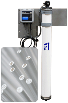
WMZ Series Wall Mount Hollow Fiber Ultrafiltration UF Systems
1,600 to 10,000 GPD
WMF Series Wall Mount Hollow Fiber Ultrafiltration UF Systems
2,200 to 20,000 GPD Wall Mount UF Systems
Both Series designed to produce clean, purified water from tap or well water, these wall-mounted systems use high efficiency ultrafiltration membranes. The filtered product water is used in commercial and residential POE/POU applications such as water stores, RO pretreatment, *whole house, laboratories, bottled water and other similar applications.
*Great alternative to whole house RO. No storage tank needed. System produces on demand water.
Call or email us for a customized quote!
Benefits of Ultrafiltration Systems
|
WMZ Series 1,600 to 10,000 GPD Economy Wall Mount Hollow Fiber UF Systems
|
Model No. |
System Capacity |
Membrane Elements |
Line Size |
System Dimensions (in/cm) |
||||
|
GPD |
m³/day |
Qty. |
Size |
Length |
Depth |
Height |
||
|
WMZ-12521A-116 |
1,600 |
6.06 |
1 |
2.5 × 21 |
½” |
28/71 |
12/30 |
26/66 |
|
WMZ-14A-116 |
10,000 |
37.85 |
1 |
4.0 × 40 |
¾” |
18/46 |
12/30 |
52/132 |
WMF Series 2,200 to 20,000 GPD Wall Mount Hollow Fiber UF Systems
|
Model No. |
System Capacity |
Membrane Elements |
Line Size |
System Dimensions (in/cm) |
||||
|
GPD |
m³/day |
Qty. |
Size |
Length |
Depth |
Height |
||
|
WMF-22521A-116 |
2,200 |
8 |
2 |
2.5 × 21 |
½” |
28/71 |
12/30 |
26/66 |
|
WMF-42521A-116 |
4,300 |
16 |
4 |
2.5 × 21 |
½” |
35/89 |
12/30 |
26/66 |
|
WMF-24A-116 |
13,000 |
50 |
2 |
4.0 × 40 |
¾” |
29/73 |
12/30 |
52/132 |
|
WMF-44A-116 |
22,000 |
83 |
4 |
4.0 × 40 |
1” |
36/91 |
12/30 |
52/132 |
Notes and Voltage
- All dimensions and weights are approximate.
- Capacity Basis: 24 hrs/day
- Systems rated at: 77°F (25°C) less than 1,500 ppm total dissolved solids (TDS) city water or natural groundwater well
- Minimum feed pressure to UF System: 40 PSI.
- Voltage: 120 volts, single phase, 60 hertz. 220 volt available upon request
- System capacity changes significantly with water temperature
- Media pretreatment recommended for source water turbidity reduction, typically for well water.
Features
Wall-Mount UF Systems Standard Equipment
Standard Equipment
- Hollow fiber ultrafiltration membranes
- PVC membrane housings/vessels
- Liquid filled system pressure gauge
- Corrosion resistant powder coated durable frame
- Boxed and palletized for shipment
- Electric actuated control valve system
- Automated system controller
- Inlet isolation valve
WMZ Economy Series Wall Mount UF Controller FeaturesController for Automatic OperationController Features:
Indicator Lights:
|
WMF Series Wall-Mount UF Systems Controller FeaturesController for Automatic OperationController Features:
Indicator Lights:
|
Applications
Applications for Wall Mount Hollow Fiber UF Systems
- Purification of surface water, groundwater and spring water to make drinking water and process water
- Pretreatment in sea water desalination plants in combination with reverse osmosis or thermal treatment
- Water for industrial use to close water cycles and a wide variety of other applications
Parts
Pretreatment and Post Treatment Options
|
System Model No. |
Carbon Filter |
UV Disinfection Post Treatment |
Multi-Media Filter Pretreatment |
1 Micron Filter Pretreatment |
Pressure Tank |
| WMZ-12521A-116 | A725 | S2Q-PA | W-MB844ET-US | A704-10-1 | A612-40 |
| WMZ-14A-116 | A725BB | S5Q-PA | W-MB1665ET-US | A704-20-1 | A612-80 |
|
WMF-22521A-116 |
A725 |
S2Q-PA |
W-MB844ET-US |
A704-10-1 |
A612-40 |
|
WMF-42521A-116 |
A725 |
S2Q-PA |
W-MB844ET-US |
A704-10-1 |
A612-40 |
|
WMF-24A-116 |
A725BB |
S5Q-PA |
W-MB1665ET-US |
A704-20-1 |
A612-80 |
|
WMF-44A-116 |
A725BB |
S8Q-PA |
W-MB1665ET-US |
A704-20-1 |
A612-80 |
ABOUT ULTRAFILTRATION
BY DR. GIL DHAWAN
Ultrafiltration is a separation process using membranes with pore sizes in the range of 0.1 to 0.001 micron. Typically, ultrafiltration will remove high molecular-weight substances, colloidal materials, and organic and inorganic polymeric molecules. Low molecular-weight organics and ions such as sodium, calcium, magnesium chloride, and sulfate are not removed. Because only high-molecular weight species are removed, the osmotic pressure differential across the membrane surface is negligible. Low applied pressures are therefore sufficient to achieve high flux rates from an ultrafiltration membrane. Flux of a membrane is defined as the amount of permeate produced per unit area of membrane surface per unit time. Generally flux is expressed as gallons per square foot per day (GFD) or as cubic meters per square meters per day.
Ultrafiltration membranes can have extremely high fluxes but in most practical applications the flux varies between 50 and 200 GFD at an operating pressure of about 50 psig in contrast, reverse osmosis membranes only produce between 10 to 30 GFD at 200 to 400 psig.
Ultrafiltration, like reverse osmosis, is a cross-flow separation process. Here liquid stream to be treated (feed) flows tangentially along the membrane surface, thereby producing two streams. The stream of liquid that comes through the membrane is called permeate. The type and amount of species left in the permeate will depend on the characteristics of the membrane, the operating conditions, and the quality of feed. The other liquid stream is called concentrate and gets progressively concentrated in those species removed by the membrane. In cross-flow separation, therefore, the membrane itself does not act as a collector of ions, molecules, or colloids but merely as a barrier to these species.
Conventional filters such as media filters or cartridge filters, on the other hand, only remove suspended solids by trapping these in the pores of the filter-media. These filters therefore act as depositories of suspended solids and have to be cleaned or replaced frequently. Conventional filters are used upstream from the membrane system to remove relatively large suspended solids and to let the membrane do the job of removing fine particles and dissolved solids. In ultrafiltration, for many applications, no prefilters are used and ultrafiltration modules concentrate all of the suspended and emulsified materials.
CONCENTRATION POLARIZATION
When a membrane is used for a separation, the concentration of any species being removed is higher near the membrane surface than it is in the bulk of the stream. This condition is known as concentration polarization and exists in all ultrafiltration and reverse osmosis separations. The result of concentration polarization is the formation of a boundary layer of substantially high concentration of substances being removed by the membrane. The thickness of the layer and its concentration depend on the mass of transfer conditions that exist in the membrane system. Membrane flux and feed flow velocity are both important in controlling the thickness and the concentration in the boundary layer. The boundary layer impedes the flow of water through the membrane and the high concentration of species in the boundary layer produces a permeate of inferior quality in ultrafiltration applications relatively high fluid velocities are maintained along the membrane surface to reduce the concentration polarization effect.
RECOVERY
Recovery of an ultrafiltration system is defined as the percentage of the feed water that is converted into the permeate, or:
R= P × 100
F
Where:
R = Recovery
P = Volume of permeate
F = Volume of Feed
ULTRAFILTRATION MEMBRANES
Ultrafiltration Membrane modules come in plate-and-frame, spiral-wound, and tubular configurations. All configurations have been used successfully in different process applications. Each configuration is especially suited for some specific applications and there are many applications where more than one configuration is appropriate. For high purity water, spiral-wound and capillary configurations are generally used. The configuration selected depends on the type and concentration of colloidal material or emulsion. For more concentrated solutions, more open configurations like plate-and-frame and tubular are used. In all configurations the optimum system design must take into consideration the flow velocity, pressure drop, power consumption, membrane fouling and module cost.
MEMBRANE MATERIALS
A variety of materials have been used for commercial ultrafiltration membranes, but polysulfone and cellulose acetate are the most common. Recently thin-film composite ultrafiltration membranes have been marketed. For high purity water applications the membrane module materials must be compatible with chemicals such as hydrogen peroxide used in sanitizing the membranes on a periodic basis.
MOLECULAR-WEIGHT CUTOFF
Pore sizes for ultrafiltration membranes range between 0.001 and 0.1 micron. However, it is more customary to categorize membranes by molecular-weight cutoff. For instance, a membrane that removes dissolved solids with molecular weights of 10,000 and higher has a molecular weight cutoff of 10,000. Obviously, different membranes even with the same molecular-weight cutoff, will have different pore size distribution. In other words, different membranes may remove species of different molecular weights to different degrees. Nevertheless, molecular-weight cutoff serves as a useful guide when selecting a membrane for a particular application.
FACTORS AFFECTING THE PERFORMANCE OF ULTRAFILTRATION
There are several factors that can affect the performance of an ultrafiltration system. A brief discussion of these is given here.
FLOW ACROSS THE MEMBRANE SURFACE
velocity if especially critical for liquids containing emulsions or suspensions. Higher flow also means higher energy consumption and larger pumps. Increasing the flow velocity also reduces the fouling of the membrane surface. Generally, an optimum flow velocity is arrived at by a compromise between the pump horsepower and increase in permeate rate.
The permeate rate increases with the flow velocity of the liquid across the membrane surface. Flow
PERFORMANCE OF ULTRAFILTRATION SYSTEM
In high purity water systems, ultrafiltration is slowly replacing the traditional 0.2-micron cartridge filters. In Japan, practically all of the semiconductor industry follows this practice. An ultrafiltration membrane with a molecular-weight cutoff of 10,000 has a nominal pore size of 0.003 micron. When an ultrafiltration membrane is used instead of a 0.2-micron cartridge filter, particle removal efficiency is greatly improved. In addition, ultrafiltration membranes are not susceptible to the problem of bacteria growing through them, as is the case with 0.2-micron filters.
In a recent study (1), the performance of an ultrafilter was compared with that of a 0.2-micron cartridge filter. Some of these results are given in Table A.
The Ultrafilter used in the study had a molecular-weight cutoff of 100,000- (pore size 0.006 micron). As the requirements for the quality of high purity water become more stringent, we can expect to see an increasing use of ultrafiltration as a final filter.
TABLE A: EFFECTIVENESS OF ULTRAFILTRATION PARTICLE COUNTS ON WATERS
|
Test Location |
0.2 Micron Filtered DI Rinse Water |
Unfiltered DI Rinse Water |
|
1 |
200-300 |
20-30* |
|
2 |
175-200 |
0-25 |
|
3 |
120 |
5 |
|
4 |
275 |
125* |
OPERATION AND MAINTENANCE
Ultrafiltration system operation and maintenance is similar to that of reverse osmosis systems. Daily records of feed and permeate flow, feed pressure and temperature, and pressure drop across the system should be kept. Membranes should be cleaned when the system permeate rate drops by 10% or more. Feed flow is critical to the operation of ultrafiltration systems. A drop in feed flow may be due to a problem in the prefilter (if any), with the flow control valve, or with the pump itself. When the system is shut down for more than two days, a bacteriocide should be circulated through the membranes. At restart, permeate should be diverted to drain until all the bacteriocide is removed.
CONCLUSIONS
Ultrafiltration will find an increasing application in the production of high purity water. The basic principles outlined here should help in the understanding and use of this technology.
REFERENCE
1Gaudet, P.W. "Point-of-use Ultrafiltration of Deionized Water and Effects of Microelectronics Device Quality, American Society for Testing and Materials", 1984.
GLOSSARY OF TERMS
- Feed - Liquid to be treated by the ultrafiltration
- Permeate - Liquid stream that passes through the
- Concentrate - Remaining Portion of the liquid stream after the permeate has been
- Recovery - Expressed as percentage, this defines the permeate rate as a fraction of the feed rate. Recovery provides an immediate measure of the maximum concentrations in the system and it affects permeate quality, pump size, power consumption and membrane
- Flux - Permeate flow per unit area of membrane per unit time (gallons/ft²/day)
- Rejection - Percent removal of a particular species by the membrane. Expressed as 1-CP CF where CP is the concentration in the permeate, and CF is the concentration in the
- Flow Velocity - Rate at which the liquid goes along the membrane surface, expresse d in length per unit time (ft/sec).
THE AUTHOR
Dr. Gil Dhawan is the president of Applied Membranes, Inc. based in Vista, CA. Dr. Dhawan has been involved in the design, development, and marketing of ultrafiltration and reverse osmosis systems for the past 35 years.


